alias Le Superbe from Mantua
- All decks are not installed at the same time.
- The lower deck (above Le Superbe) is set up first. In the case of Le Superbe, it must be cut crosswise to get through the supports of gangways.
- Once the lower deck is reglued, place its floor, sand and varnish it.
- Place its gratings
and its stairs. Varnish them.
- If gun carriages are to be installed, the case is presented farther.
>>>>>>>>>>>>>>>>>>>>>>>>>>>>>>>>>>>>
Gun Carriages on the Second Deck
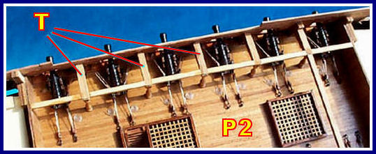
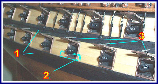
- Put the gun carriages on the second deck (P2) while its access is still easy.
- Put also the columns at the ends of the supports (T) of gangways
.
- Put the rigging of gun carriages to add details to the model.
- The guns will be placed later on their carriages.
>>>>>>>>>>>>>>>>>>>>>>>>>>>>>>>>>>>>
Errors from a Few Kits
- The bad site of the ports seems a scouring problem of the kits.
- Why the manufacturers add this anomaly to their production? It is a mystery.
- Certain manufacturers propose to you panels precut with the open ports for two or three batteries. This approach me leave perplexed, because it cannot reproduce the curves of the hull accurately.
- The solution is however simple, it is the site of the couples which east fixes with the site of the ports and not the opposite.
- To be obliged to cross in the couples of the sites of ports and guns is not normal.
- But it is possible, fortunately for the model maker anxious to make an authentic model.
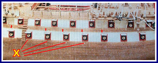
Photograph of Le Superbe by Mantua
- Let us note that the lower gunports (X) are obviously not in their place, in the middle of the upper gunports (red marks).
- This building error can be corrected.
- The space between the gunports must remain the same one, as well for the first battery
(nearest to water) as for the second battery.
>>>>>>>>>>>>>>>>>>>>>>>>>>>>>>>>>>>>
Planning Pine Gun Supports
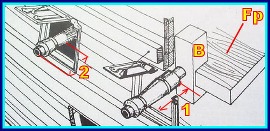
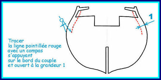
Sketch of Le Superbe by Mantua
- Here is the example of a 74 guns:
- Small blocks of wood (B) must be glued on the edge of the false decks (Fp), to receive the dummy barrels
.
- The distance 1 between the blocks and the hull should be constant, the barrels having all the same length.
- But this distance is not constant, the sides of the false decks are not parallel to the sides of the hull.
- To calculate the distance 1, take the length of the barrel without its point and remove the distance 2 (6mm) + the thickness of the hull.
- 1 = barrel length without its point - (6mm + thickness of the hull).
- The distance 1 is traced on all the bulkheads, on both sides and both faces.
- The layouts can be made before assembling "keel and bulkheads".
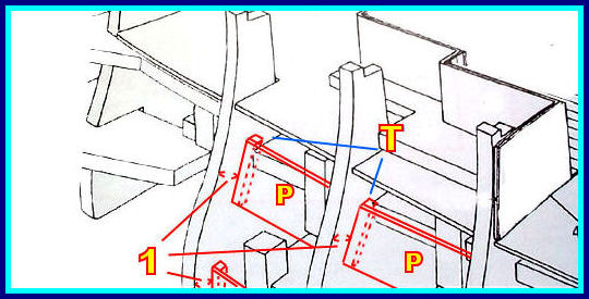
Sketch of Le Superbe by Mantua
- To correct the bad location of the blocks B, we place between the bulkheads the small planks P (30mm x 4mm).
- Glue these small planks P on cross-beams T.
>>>>>>>>>>>>>>>>>>>>>>>>>>>>>>>>>>>>
Copyright © 2011 Hubert SicardBulkheads To Be Cut Out
- To simplify work, we could prepare the opening of the gunports at the beginning of the model assembly.
- This anticipated preparation would be done thus before gluing the bulkheads on the keel.
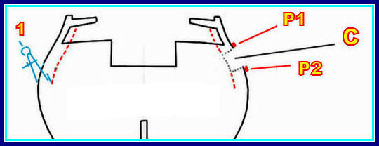
- Draw, on the sides of the bulkheads, the line 1 the calculation of which has been done above .
- Assemble, without gluing them, the bulkheads on the keel.
- Attach the bulkheads so that they are holding well to the keel (steel wire or adhesive tape).
- Then fix temporarily the first wales (P1) located under the second battery.
- Pose temporarily the second wales (P2) parallel to the first wale.
- Mark on the edge of the bulkheads the position of this second wale.
- Disassemble the provisional assembly of the keel and the bulkheads.
- Cut out in the edgee of the bulkheads, above the mark of the second wale, spaces (C) for the installation of the frames.
>>>>>>>>>>>>>>>>>>>>>>>>>>>>>>>>>>>>
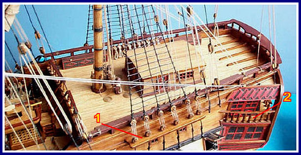
- For all the parts having to be covered with a floor (channels (1), balconies (2) of gallery, masttops, etc.), look carefully at plans if you can cover them before gluing them on the model.
- That will simplify the planking work a lot.
- However, a between-deck with its floor laid is no more very flexible for a later installation.
>>>>>>>>>>>>>>>>>>>>>>>>>>>>>>>>>>>>
Assembling Metal Gunport Lids

- 1. Small file to clean the axis of the lids.
- 2. A 45░ plastic section: 19.5 x 19.5mm of side (3/4" x 3/4").
- 3. A 2 x 2mm (3/32" x 3/32") strip, glued in the middle of one side of the section. This strip gives a larger opening to the lids.
- 4. 5 Minute Epoxy glue to assemble lids and frames.
- 5. Assembled lids and frames.
- 1. The wales are dyed with Indian ink before being installed.
- 2. Glue the guns with point, build a small guide to bore the hole of the points (take a strip of the same section as the openings of the gunports, cut a length of 15mm, make in the middle of this small piece a well centered hole of the diameter of the points). The guns are glued with 5 Minute Epoxy glue. Put a small wedge under the cannons, for holding them properly in place during the complete drying of epoxy (around 24 hours).
- 3. The swing cables of the lids are made with a 0.5mm cable hardened with carpenter glue.
>>>>>>>>>>>>>>>>>>>>>>>>>>>>>>>>>>>>
- The explanations of manufacturers for the assembly of the gallery
are always very enigmatic.
- However, the assembly of an gallery is relatively simple.
- It is also a part of the model on which one can make the most improvements.
- One could go even so far as opening the windows and covering the interior deck with a floor. Without speaking about the balconies which can be easily improved.
- The gallery generally includes a wardroom
, in which miniature chairs and table would be almost possible.
- And to finish, doors opening the wardroom towards quarter galleries
.
>>>>>>>>>>>>>>>>>>>>>>>>>>>>>>>>>>>>
- At first view, MANTUA seems to propose a single dimension of launch for all its models. Either in a 1:50 scale or in a 1:75 scale.
- And this without noticing any false size in the launches.
- On the other hand, no oars provided with these launches were in scale.
- Such a detail is not quite obvious at once but must be corrected when we discover it.
- On the Astrolabe, the error was too visible to be ignored.
The Launches of the Algonquin (First version)
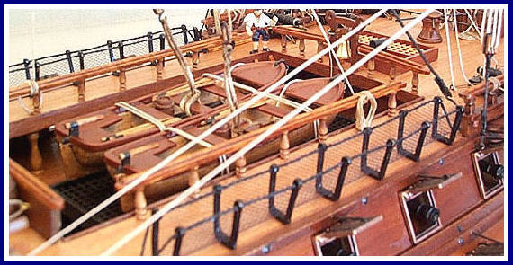
- As for my first Algonquin, alias Le Superbe, three launches were included in the kit.
- Not wanting to block completely the view on the second battery below the gangways, I only used two of them.
- I had not yet noted that the oars were too small.
The Launches of the Algonquin (Second version)
- As for this second Algonquin, having set a complete rigging on the artillery of the second battery, I wanted it to be visible.
- So a single launch was set on this deck.
- A second one was placed at the back of the mainmast to replace a bilge pump not very realistic.
Visitors Wooden Ships Modeling for the Dummies Visitors


